Astable 555 Timer Schematic - 555 Timer Basics Astable Mode / Unlike monostable multivibrator mode it doesn't have any stable state, it has two quasi stable state (high and low).. In this mode, the circuit of the ic 555 timer produces the continuous pulses with exact frequency primarily based on the value of the two resistors and. We have seen in the last few tutorials that the 555 timer can be configured with externally connected components as multivibrators, oscillators and timers, with timing intervals ranging from a few microseconds to many hours. Resistor r3 is just there to limit the. For detailed explanation, check it out. When the voltage across c1 reaches 2/3 of the supply voltage.
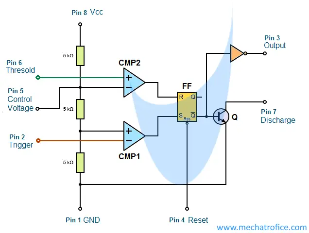
The following schematic depicts the internal circuit of the ic 555 operating in astable mode. In astable mode, capacitor c1 charges through resistors r1 and r2. The 555 is also very versatile, and can be used. Monostable 555 timer circuits will automatically trigger and start a timing cycle when power is applied to the circuit. The period is the length of time it takes for.
555 Timer from sound-au.com The following schematic depicts the internal circuit of the ic 555 operating in astable mode. The 555 timer shown above is configured as an astable circuit. The rc timing circuit incorporates r 1 , r 2 and c. Larger values will make the led blink slower, while smaller values will make the led blink faster. In astable mode, the output from the 555 timer is a continuous pulse waveform of a specific frequency that depends on the values of the two resistors (r a and r b) and capacitor (c) used in the circuit (fig 1) according to the equation below.astable mode is closely related to monostable mode (discussed in step 2), you can see that the schematic is nearly the same. In astable mode, the 555 timer behaves as an oscillator. In an astable circuit, the output voltage alternates between vcc and 0 volts on a continual basis. This time period is determined by the expression t=1.
The 555 timer ic is an integrated circuit (chip) used in a variety of timer, pulse generation, and oscillator applications.
It is a slave to the a timer. Incidentally, a complementary (opposite) output q is available from the collector of the other transistor. The output will keep switching between high and low forever. The 555 timer astable arrangement creates a square wave with time high and time low. The period is the length of time it takes for. In an astable circuit, the output voltage alternates between vcc and 0 volts on a continual basis. Basic 555 astable multivibrator circuit. Complete 555 timer circuit reset switch. This tutorial provides sample circuits to set up a 555 timer in monostable, astable, and bistable modes as well as an in depth discussion of how the 555 timer works and how to choose components to use with it. Resistor r3 is just there to limit the. The 555 timer is capable of being used in astable and monostable circuits. The following image shows a simplified circuit of 555 timer ic in astable mode. 10+ circuit diagram of pwm using ic 555.
This modification enables the user to adjust the on/off periods of the ic separately, and therefore achieve the desired pwm rate quickly. The timer's internal circuitry is largely responsible for this triggering but it is also caused stray or installed capacitance at the trigger input of the timer. Using the 555 timer ic in special or unusual circuits. In an astable circuit, the output voltage alternates between vcc and 0 volts on a continual basis. 555 timer astable mode circuit diagram.
555 Multivibrator Circuits Tutorial Astable Monostable Bistable from mechatrofice.com The 555 is also very versatile, and can be used. The timer's internal circuitry is largely responsible for this triggering but it is also caused stray or installed capacitance at the trigger input of the timer. That means it works as an oscillator. An astable circuit describes a device that has two temporary unstable states, and the device alternates between these states with a period and duty cycle determined by the values of circuit components. The designing and working of astable multivibrator using a 555 timer ic is done by using ransistors and operational amplifiers.the 555 timer ic affords exact time delay from ms to hours. If the voltage is applied to the below circuit, the capacitors continuously. The rc timing circuit incorporates r 1 , r 2 and c. 555 timer ic is an integrated circuit used in a variety of timer, pulse generation circuit, and oscillator circuit applications.
Each mode of operation indicates a circuit diagram and its output.
The working modes of a 555 timer are astable, bistable, and monostable. No external triggering is required in astable mode, it automatically interchange its two states on a particular interval, hence generates a rectangular waveform. The 555 timer ic is an integrated circuit (chip) used in a variety of timer, pulse generation, and oscillator applications. While the capacitor is charging, the output is high. In this mode, the circuit of the ic 555 timer produces the continuous pulses with exact frequency primarily based on the value of the two resistors and. The rc timing circuit incorporates r 1 , r 2 and c. When the 555 timer is in astable mode it means that the output will never be stable. 555 timer astable mode circuit diagram. Working modes of 555 timer ic. The timer's internal circuitry is largely responsible for this triggering but it is also caused stray or installed capacitance at the trigger input of the timer. It is a slave to the a timer. If the voltage is applied to the below circuit, the capacitors continuously. In astable mode, the 555 timer behaves as an oscillator.
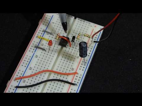
When the voltage across c1 reaches 2/3 of the supply voltage. To observe the 555 timer in astable mode, let's build a circuit that uses the 555 timer's oscillating output to make an led flash on and off: I made a dedicated tutorial on astable multivibrator using 555 timer. The designing and working of astable multivibrator using a 555 timer ic is done by using ransistors and operational amplifiers.the 555 timer ic affords exact time delay from ms to hours. That means it works as an oscillator.
555 Timer Electronics Astable Mode Circuit Step By Step Build Demonstration By Electronzap Youtube from i.ytimg.com An astable circuit describes a device that has two temporary unstable states, and the device alternates between these states with a period and duty cycle determined by the values of circuit components. The rc timing circuit incorporates r 1 , r 2 and c. Circuits for both astable and monostable versions of this method are shown on the diagram. 555 timer ic is an integrated circuit used in a variety of timer, pulse generation circuit, and oscillator circuit applications. Larger values will make the led blink slower, while smaller values will make the led blink faster. The 555 timer astable arrangement creates a square wave with time high and time low. This tutorial provides sample circuits to set up a 555 timer in monostable, astable, and bistable modes as well as an in depth discussion of how the 555 timer works and how to choose components to use with it. The 555 timer is an integrated circuit, it is extremely versatile and can be used to build lots of different circuits.
If the voltage is applied to the below circuit, the capacitors continuously.
The following schematic depicts the internal circuit of the ic 555 operating in astable mode. Resistor r3 is just there to limit the. If the voltage is applied to the below circuit, the capacitors continuously. Working modes of 555 timer ic. I made a dedicated tutorial on astable multivibrator using 555 timer. In astable mode, the output from the 555 timer is a continuous pulse waveform of a specific frequency that depends on the values of the two resistors (r a and r b) and capacitor (c) used in the circuit (fig 1) according to the equation below.astable mode is closely related to monostable mode (discussed in step 2), you can see that the schematic is nearly the same. No external triggering is required in astable mode, it automatically interchange its two states on a particular interval, hence generates a rectangular waveform. By selecting values for r1, r2 and c we can determine the period/frequency and the duty cycle. When the voltage across c1 reaches 2/3 of the supply voltage. Lm555 complimentary outputs schematic timer b in this method acts as a voltage comparator and has no timing function. The 555 timer is capable of being used in astable and monostable circuits. Many times when you see a project with flashing leds, it's a 555 timer at work. Here the time period is the total time it takes to complete one on/off cycle (t 1 +t 2), while duty cycle is the percentage of total time for which the.
The 555 timer is capable of being used in astable and monostable circuits 555 timer schematic. The 555 has three main operating modes, monostable, astable, and bistable.